Computer organization refers to the operational unit and their interconnection that realise the architectural specification.
Computer organization deals with how different part of a computer are organised and how various operations are performed between different part to do a specific task.
The organization of the computer is defined by its internal registers ,timing and control structure ,and set of instruction that is uses.
Instruction & Instruction Codes
Instruction:-
Computer instructions are a set of machine language instructions that a particular processor understands and executes. A computer performs tasks on the basis of the instruction provided.
An instruction comprises of groups called fields. These fields include:
- The Operation code (Opcode) field which specifies the operation to be performed.
- The Address field which contains the location of the operand, i.e., register or memory location.
- The Mode field which specifies how the operand will be located.

A basic computer has three instruction code formats which are:
- Memory – reference instruction
- Register – reference instruction
- Input-Output instruction
Memory – reference instruction

In Memory-reference instruction, 12 bits of memory is used to specify an address and one bit to specify the addressing mode ‘I’.
Register – reference instruction

The Register-reference instructions are represented by the Opcode 111 with a 0 in the leftmost bit (bit 15) of the instruction.
Note: The Operation code (Opcode) of an instruction refers to a group of bits that define arithmetic and logic operations such as add, subtract, multiply, shift, and compliment.
A Register-reference instruction specifies an operation on or a test of the AC (Accumulator) register.
Input-Output instruction

Just like the Register-reference instruction, an Input-Output instruction does not need a reference to memory and is recognized by the operation code 111 with a 1 in the leftmost bit of the instruction. The remaining 12 bits are used to specify the type of the input-output operation or test performed.
Note
- The three operation code bits in positions 12 through 14 should be equal to 111. Otherwise, the instruction is a memory-reference type, and the bit in position 15 is taken as the addressing mode I.
- When the three operation code bits are equal to 111, control unit inspects the bit in position 15. If the bit is 0, the instruction is a register-reference type. Otherwise, the instruction is an input-output type having bit 1 at position 15.
Instruction Set Completeness
A set of instructions is said to be complete if the computer includes a sufficient number of instructions in each of the following categories:
- Arithmetic, logical and shift instructions
- A set of instructions for moving information to and from memory and processor registers.
- Instructions which controls the program together with instructions that check status conditions.
- Input and Output instructions
Arithmetic, logic and shift instructions provide computational capabilities for processing the type of data the user may wish to employ.
A huge amount of binary information is stored in the memory unit, but all computations are done in processor registers. Therefore, one must possess the capability of moving information between these two units.
Program control instructions such as branch instructions are used change the sequence in which the program is executed.
Input and Output instructions act as an interface between the computer and the user. Programs and data must be transferred into memory, and the results of computations must be transferred back to the user.
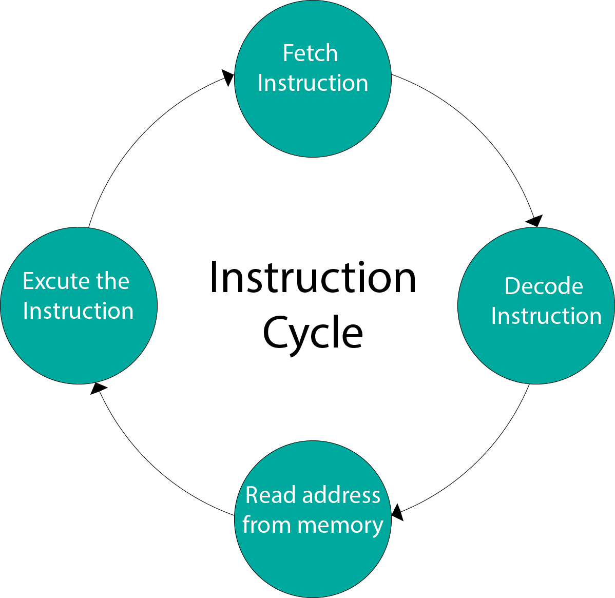
Instruction Cycle
A program residing in the memory unit of a computer consists of a sequence of instructions. These instructions are executed by the processor by going through a cycle for each instruction.
In a basic computer, each instruction cycle consists of the following phases:
- Fetch instruction from memory.
- Decode the instruction.
- Read the effective address from memory.
- Execute the instruction.
Input-Output Configuration
In computer architecture, input-output devices act as an interface between the machine and the user.
Instructions and data stored in the memory must come from some input device. The results are displayed to the user through some output device.
The following block diagram shows the input-output configuration for a basic computer.
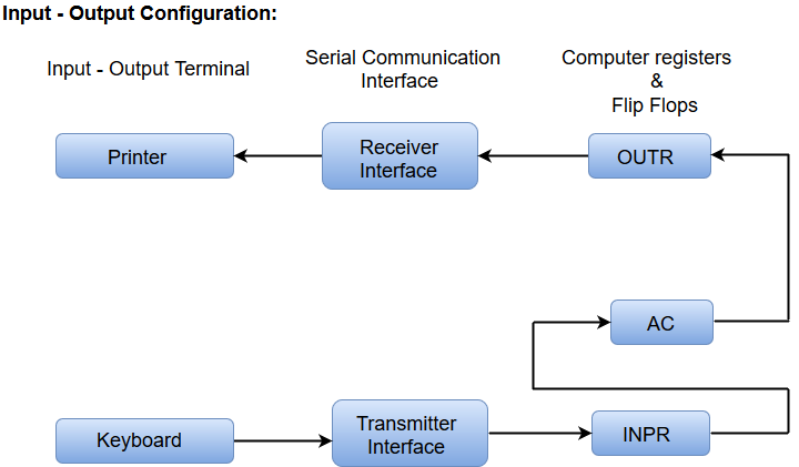
- The input-output terminals send and receive information.
- The amount of information transferred will always have eight bits of an alphanumeric code.
- The information generated through the keyboard is shifted into an input register ‘INPR’.
- The information for the printer is stored in the output register ‘OUTR’.
- Registers INPR and OUTR communicate with a communication interface serially and with the AC in parallel.
- The transmitter interface receives information from the keyboard and transmits it to INPR.
- The receiver interface receives information from OUTR and sends it to the printer serially.
Design of a Basic Computer
A basic computer consists of the following hardware components.
- A memory unit with 4096 words of 16 bits each
- Registers: AC (Accumulator), DR (Data register), AR (Address register), IR (Instruction register), PC (Program counter), TR (Temporary register), SC (Sequence Counter), INPR (Input register), and OUTR (Output register).
- Flip-Flops: I, S, E, R, IEN, FGI and FGO
Note: FGI and FGO are corresponding input and output flags which are considered as control flip-flops.
- Two decoders: a 3 x 8 operation decoder and 4 x 16 timing decoder
- A 16-bit common bus
- Control Logic Gates
- The Logic and Adder circuits connected to the input of AC.
