components of data communication network
- Data
- Sender
- Receiver
- Transmission Medium
- Protocol

Data
Communication of data means a message or data will be transmitted from one device and will be received in the destination or target device. Thus the first component in a data communication network is data or message to that needs to be delivered and received. Data or message can be of various forms such as text, audio, video, image or combinations of these forms etc.
Sender
A source must send that to a destination. This source is the sender. The device that sends the data to the destination or target is the Sender. It can be a computer, cell phone, video camera and so on.
Receiver
The destination of a transmitted data is the receiver which will receive the data. The device that receives the data is the Receiver. A receiver can again be a computer, cell phone, video camera and so on.
Transmission medium
In data communication network, the transmission medium is the physical path for the data to travel to its destination. Receiver receives the data at one end of this path and the sender sent from another end of the path. Transmission medium could be like twisted-pair cable, coaxial cable, fiber-optic cable etc.
Protocol
A protocol is nothing but a set of rules that applies on the full data communication procedure. This is like an agreement between the two devices to successfully communicate with each other. For example, how to send the data, how the data will be traveling, how to ensure that full data has received, how to handle errors in transmission etc. Both devices follow the same set of rules or protocol so that they understand each other.
DISTRIBUTED PROCESSING
Data communication and Networking use distributed processing, during which a task is split among multiple computers. rather than one large machine being liable for all aspects of a process, each separate computer(usually a private computer or workstation) handles a subset.
SECURITY/ENCAPSULATION – An system designer can limit the type of interaction that a given user can have with the whole system. for instance, a bank can allow users access to their own accounts through an automatic teller machine (ATM) without allowing them access to the bank’s entire database.
DISTRIBUTED DATABASE – nobody system must provide storage capacity for the whole database. for instance, the planet-wide web gives users access to information that will be actually stored and manipulate anywhere on the web.
FASTER PROBLEM SOLVING – Multiple computers performing on parts of a drag currently often can solve the matter faster than one working alone. for instance, networks of pc have broken encryption codes that were presumed to be unbreakable due to the quantity of your time it might take one computer to crack them.
SECURITY THROUGH REDUNDANCY – Multiple computers running an equivalent program at an equivalent time can provide security through redundancy. for instance, within the spacecraft, three computers run an equivalent program in order that if one features an error, the opposite two can override it.
COLLABORATIVE PROCESSING – Both multiple and computer users may interact on a task. for instance, in multiuser network games, the action of every player is visible to and affects all the others.
standards and organizations
The primary reason for standards is to ensure that hardware and software produced by different vendors can work together. Without networking standards, it would be difficult—if not impossible—to develop networks that easily share information. Standards also mean that customers are not locked into one vendor. They can buy hardware and software from any vendor whose equipment meets the standard. In this way, standards help to promote more competition and hold down prices.
The use of standards makes it much easier to develop software and hardware that link different networks because software and hardware can be developed one layer at a time.
The Standards-Making Process
There are two types of standards: formal and de facto. A formal standard is developed by an official industry or government body. For example, there are formal standards for applications such as Web browsers (e.g., HTTP, HTML), for network layer software (e.g., IP), data link layer software (e.g., Ethernet IEEE 802.3), and for physical hardware (e.g., V.90 modems). Formal standards typically take several years to develop, during which time technology changes, making them less useful.
De facto standards are those that emerge in the marketplace and are supported by several vendors but have no official standing. For example, Microsoft Windows is a product of one company and has not been formally recognized by any standards organization, yet it is a de facto standard. In the communications industry, de facto standards often become formal standards once they have been widely accepted.
The formal standardization process has three stages: specification, identification of choices, and acceptance. The specification stage consists of developing a nomenclature and identifying the problems to be addressed. In the identification of choices stage, those working on the standard identify the various solutions and choose the optimum solution from among the alternatives. Acceptance, which is the most difficult stage, consists of defining the solution and getting recognized industry leaders to agree on a single, uniform solution. As with many other organizational processes that have the potential to influence the sales of hardware and software, standards-making processes are not immune to corporate politics and the influence of national governments.
International Organization for Standardization One of the most important standards-making bodies is the International Organization for Standardization (ISO),2 which makes technical recommendations about data communication interfaces (see www.iso.org). ISO is based in Geneva, Switzerland. The membership is composed of the national standards organizations of each ISO member country.
International Telecommunications Union—Telecommunications Group The Telecommunications Group (ITU-T) is the technical standards-setting organization of the United Nations International Telecommunications Union, which is also based in Geneva (see http://www.itu.int). ITU is composed of representatives from about 200 member countries. Membership was originally focused on just the public telephone companies in each country, but a major reorganization in 1993 changed this, and ITU now seeks members among public- and private-sector organizations who operate computer or communications networks (e.g., RBOCs) or build software and equipment for them (e.g., AT&T).
American National Standards Institute The American National Standards Institute (ANSI) is the coordinating organization for the U.S. national system of standards for both technology and nontechnology (see http://www.ansi.org). ANSI has about 1,000 members from both public and private organizations in the United States. ANSI is a standardization organization, not a standards-making body, in that it accepts standards developed by other organizations and publishes them as American standards. Its role is to coordinate the development of voluntary national standards and to interact with ISO to develop national standards that comply with ISO’s international recommendations. ANSI is a voting participant in the ISO.
How Network Protocols 1.3 Become Standards
MANAGEMENT FOCUS
There are many standards organizations around the world, but perhaps the best known is the Internet Engineering Task Force (IETF). IETF sets the standards that govern how much of the Internet operates.
The IETF, like all standards organizations, tries to seek consensus among those involved before issuing a standard. Usually, a standard begins as a protocol (i.e., a language or set of rules for operating) developed by a vendor (e.g., HTML [Hypertext Markup Language]). When a protocol is proposed for standardization, the IETF forms a working group of technical experts to study it. The working group examines the protocol to identify potential problems and possible extensions and improvements, then issues a report to the IETF.
If the report is favorable, the IETF issues a request for comment (RFC) that describes the proposed standard and solicits comments from the entire world. Most large software companies likely to be affected by the proposed standard prepare detailed responses. Many ”regular” Internet users also send their comments to the IETF.
The IETF reviews the comments and possibly issues a new and improved RFC, which again is posted for more comments. Once no additional changes have been identified, it becomes a proposed standard.
Usually, several vendors adopt the proposed standard and develop products based on it. Once at least two vendors have developed hardware or software based on it and it has proven successful in operation, the proposed standard is changed to a draft standard. This is usually the final specification, although some protocols have been elevated to Internet standards, which usually signifies mature standards not likely to change.
The process does not focus solely on technical issues; almost 90 percent of the IETF’s participants work for manufacturers and vendors, so market forces and politics often complicate matters. One former IETF chairperson who worked for a hardware manufacturer has been accused of trying to delay the standards process until his company had a product ready, although he and other IETF members deny this. Likewise, former IETF directors have complained that members try to standardize every product their firms produce, leading to a proliferation of standards, only a few of which are truly useful.
Institute of Electrical and Electronics Engineers The Institute of Electrical and Electronics Engineers (IEEE) is a professional society in the United States whose Standards Association (IEEE-SA) develops standards (see http://www.standards.ieee.org). The IEEE-SA is probably most known for its standards for LANs. Other countries have similar groups; for example, the British counterpart of IEEE is the Institution of Electrical Engineers (IEE).
Internet Engineering Task Force The IETF sets the standards that govern how much of the Internet will operate (see http://www.ietf.org). The IETF is unique in that it doesn’t really have official memberships. Quite literally anyone is welcome to join its mailing lists, attend its meetings, and comment on developing standards.
Common Standards
There are many different standards used in networking today. Each standard usually covers one layer in a network. Figure 1.5 outlines some of the most commonly used standards. At this point, these models are probably just a maze of strange names and acronyms to you, but by the end of the topic, you will have a good understanding of each of these. Figure 1.5 provides a brief road map for some of the important communication technologies we discuss in this topic.
For now, there is one important message you should understand from Figure 1.5: For a network to operate, many different standards must be used simultaneously. The sender of a message must use one standard at the application layer, another one at the transport layer, another one at the network layer, another one at the data link layer, and another one at the physical layer. Each layer and each standard is different, but all must work together to send and receive messages.
| Layer | Common Standards |
| 5. Application layer | HTTP, HTML (Web) MPEG, H.323 (audio/video) SMTP, IMAP, POP (e-mail) |
| 4. Transport layer | TCP (Internet and LANs) SPX (Novell LANs) |
| 3. Network layer | IP (Internet and LANs) IPX (Novell LANs) |
| 2. Data link layer | Ethernet (LAN) Frame relay (WAN) T1 (MAN and WAN) |
| 1. Physical layer | RS-232C cable (LAN) Category 5 cable (LAN) V.92 (56 Kbps modem) |
HTML = Hypertext Markup Language; HTTP = Hypertext Transfer Protocol; IMAP = Internet Message Access Protocol; IP = Internet Protocol; IPX = internetwork package exchange; LAN = local area network; MPEG = Motion Picture Experts Group; POP = Post Office Protocol; SPX = sequenced packet exchange; TCP = Transmission Control Protocol
Either the sender and receiver of a message must use the same standards or, more likely, there are devices between the two that translate from one standard into another. Because different networks often use software and hardware designed for different standards, there is often a lot of translation between different standards.
LINE CONFIGURATION IN COMPUTER NETWORK
Line configuration in a computer network refers to the way 2 or more communication devices are attached to a link.
A link is the physical communication pathway that transfers data from one device to a different one.
For the purposes of visualization, it is easy to imagine any link as a line drawn between two points.
For communication to occur, two devices must be connected in how to an equivalent link at an equivalent time.
Line configuration explains the attachment of communication devices to a link.
There are two types of line configurations:-
- point-to-point
- Mmultipoint.
LINE CONFIGURATION TYPES
Point-to-Point
A point-to-point network provides a fanatical link between two devices. The entire capacity of the channel is reserved for transmission between those 2 devices.
Most point-to-point line configurations have an actual length of wire or cable to attach the 2 ends, but other options, like microwave or satellite links, also are possible.
When you change T.V channels by infrared remote, you’re establishing a point-to-point line configuration between the remote and therefore the television’s system.
Point-to-point topology is taken into account to be one of the simplest and most conventional network topologies. It is also the simplest to establish and understand.
To visualize, one can consider the point-to-point network topology as two phones connected end to end for two-way communication.
Multipoint
A multipoint (also called multidrop) is one during which quite two specific devices share one link.
In multipoint surroundings, the capability of the channel is shared, either spatially or temporally.
If several devices can use the link simultaneously, it’s a spatially shared line configuration.
If users must alternate, it’s a time-shared line configuration in the computer network.
More than two devices share the Link that’s the capacity of the channel is shared now. With shared capacity, there are often two possibilities during a Multipoint Line Config:
Spatial Sharing: If many devices will share the link at the same time, it’s known as Spatially shared line- configuration.
Temporal (Time) Sharing: If users must alternate using the link, then it’s called Temporally shared or Time Shared Line-Configuration.
Topology
Network topology refers to how various nodes, devices, and connections on your network are physically or logically arranged in relation to each other. Think of your network as a city, and the topology as the road map. Just as there are many ways to arrange and maintain a city—such as making sure the avenues and boulevards can facilitate passage between the parts of town getting the most traffic—there are several ways to arrange a network. Each has advantages and disadvantages and depending on the needs of your company, certain arrangements can give you a greater degree of connectivity and security.
There are two approaches to network topology: physical and logical. Physical network topology, as the name suggests, refers to the physical connections and interconnections between nodes and the network—the wires, cables, and so forth. Logical network topology is a little more abstract and strategic, referring to the conceptual understanding of how and why the network is arranged the way it is, and how data moves through it.
Why Is Network Topology Important?
The layout of your network is important for several reasons. Above all, it plays an essential role in how and how well your network functions. Choosing the right topology for your company’s operational model can increase performance while making it easier to locate faults, troubleshoot errors, and more effectively allocate resources across the network to ensure optimal network health. A streamlined and properly managed network topology can increase energy and data efficiency, which can in turn help to reduce operational and maintenance costs.
The design and structure of a network are usually shown and manipulated in a software-created network topology diagram. These diagrams are essential for a few reasons, but especially for how they can provide visual representations of both physical and logical layouts, allowing administrators to see the connections between devices when troubleshooting.
The way a network is arranged can make or break network functionality, connectivity, and protection from downtime. The question of, “What is network topology?” can be answered with an explanation of the two categories in the network topology.
- Physical – The physical network topology refers to the actual connections (wires, cables, etc.) of how the network is arranged. Setup, maintenance, and provisioning tasks require insight into the physical network.
- Logical – The logical network topology is a higher-level idea of how the network is set up, including which nodes connect to each other and in which ways, as well as how data is transmitted through the network. Logical network topology includes any virtual and cloud resources.
Effective network management and monitoring require a strong grasp of both the physical and logical topology of a network to ensure your network is efficient and healthy.
Types of Network Topology
Network Topology is the schematic description of a network arrangement, connecting various nodes(sender and receiver) through lines of connection.
BUS Topology
Bus topology is a network type in which every computer and network device is connected to single cable. When it has exactly two endpoints, then it is called Linear Bus topology.
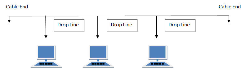
Features of Bus Topology
- It transmits data only in one direction.
- Every device is connected to a single cable
Advantages of Bus Topology
- It is cost effective.
- Cable required is least compared to other network topology.
- Used in small networks.
- It is easy to understand.
- Easy to expand joining two cables together.
Disadvantages of Bus Topology
- Cables fails then whole network fails.
- If network traffic is heavy or nodes are more the performance of the network decreases.
- Cable has a limited length.
- It is slower than the ring topology.
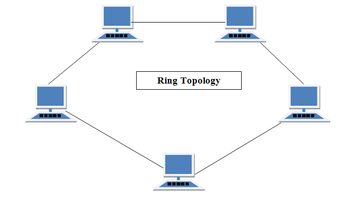
RING Topology
It is called ring topology because it forms a ring as each computer is connected to another computer, with the last one connected to the first. Exactly two neighbours for each device.
Features of Ring Topology
- A number of repeaters are used for Ring topology with large number of nodes, because if someone wants to send some data to the last node in the ring topology with 100 nodes, then the data will have to pass through 99 nodes to reach the 100th node. Hence to prevent data loss repeaters are used in the network.
- The transmission is unidirectional, but it can be made bidirectional by having 2 connections between each Network Node, it is called Dual Ring Topology.
- In Dual Ring Topology, two ring networks are formed, and data flow is in opposite direction in them. Also, if one ring fails, the second ring can act as a backup, to keep the network up.
- Data is transferred in a sequential manner that is bit by bit. Data transmitted, has to pass through each node of the network, till the destination node.
Advantages of Ring Topology
- Transmitting network is not affected by high traffic or by adding more nodes, as only the nodes having tokens can transmit data.
- Cheap to install and expand
Disadvantages of Ring Topology
- Troubleshooting is difficult in ring topology.
- Adding or deleting the computers disturbs the network activity.
- Failure of one computer disturbs the whole network.
STAR Topology
In this type of topology all the computers are connected to a single hub through a cable. This hub is the central node and all others nodes are connected to the central node.
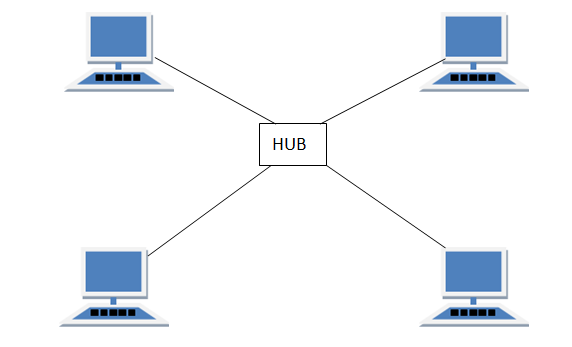
Features of Star Topology
- Every node has its own dedicated connection to the hub.
- Hub acts as a repeater for data flow.
- Can be used with twisted pair, Optical Fibre or coaxial cable.
Advantages of Star Topology
- Fast performance with few nodes and low network traffic.
- Hub can be upgraded easily.
- Easy to troubleshoot.
- Easy to setup and modify.
- Only that node is affected which has failed, rest of the nodes can work smoothly.
Disadvantages of Star Topology
- Cost of installation is high.
- Expensive to use.
- If the hub fails then the whole network is stopped because all the nodes depend on the hub.
- Performance is based on the hub that is it depends on its capacity
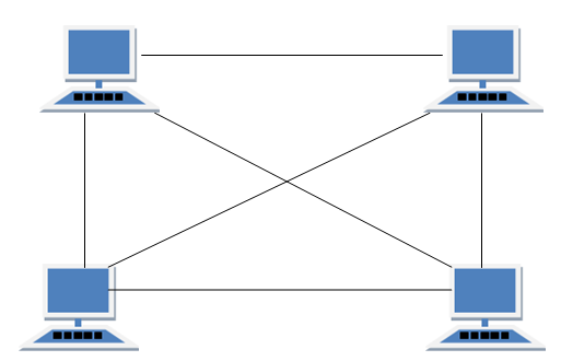
MESH Topology
It is a point-to-point connection to other nodes or devices. All the network nodes are connected to each other. Mesh has n(n-1)/2 physical channels to link n devices.
There are two techniques to transmit data over the Mesh topology, they are :
- Routing
- Flooding
MESH Topology: Routing
In routing, the nodes have a routing logic, as per the network requirements. Like routing logic to direct the data to reach the destination using the shortest distance. Or, routing logic which has information about the broken links, and it avoids those node etc. We can even have routing logic, to re-configure the failed nodes.
MESH Topology: Flooding
In flooding, the same data is transmitted to all the network nodes, hence no routing logic is required. The network is robust, and the its very unlikely to lose the data. But it leads to unwanted load over the network.
Types of Mesh Topology
- Partial Mesh Topology : In this topology some of the systems are connected in the same fashion as mesh topology but some devices are only connected to two or three devices.
- Full Mesh Topology : Each and every nodes or devices are connected to each other.
Features of Mesh Topology
- Fully connected.
- Robust.
- Not flexible.
Advantages of Mesh Topology
- Each connection can carry its own data load.
- It is robust.
- Fault is diagnosed easily.
- Provides security and privacy.
Disadvantages of Mesh Topology
- Installation and configuration is difficult.
- Cabling cost is more.
- Bulk wiring is required.
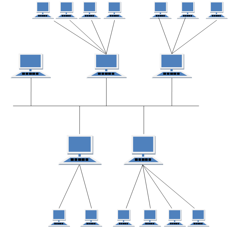
TREE Topology
It has a root node and all other nodes are connected to it forming a hierarchy. It is also called hierarchical topology. It should at least have three levels to the hierarchy.
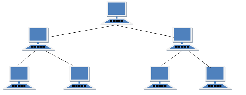
Features of Tree Topology
- Ideal if workstations are located in groups.
- Used in Wide Area Network.
Advantages of Tree Topology
- Extension of bus and star topologies.
- Expansion of nodes is possible and easy.
- Easily managed and maintained.
- Error detection is easily done.
Disadvantages of Tree Topology
- Heavily cabled.
- Costly.
- If more nodes are added maintenance is difficult.
- Central hub fails, network fails.
HYBRID Topology
It is two different types of topologies which is a mixture of two or more topologies. For example if in an office in one department ring topology is used and in another star topology is used, connecting these topologies will result in Hybrid Topology (ring topology and star topology).
Features of Hybrid Topology
- It is a combination of two or topologies
- Inherits the advantages and disadvantages of the topologies included
Advantages of Hybrid Topology
- Reliable as Error detecting and trouble shooting is easy.
- Effective.
- Scalable as size can be increased easily.
- Flexible.
Disadvantages of Hybrid Topology
- Complex in design.
- Costly.
Introduction to Transmission Modes
Transmission mode or communication mode is referred to as transmission of data between two devices using a communication channel that includes an optical fiber, copper wires, wireless channels, and various storage media. The data that gets transmitted is in the form of electromagnetic waves. There are various ways of data transmission where the message that is passed is in the sequence of pulses using digital modulation. The transmission mode of data was first introduced in a computer networking system during the 1940s in modems, then in LANs, WANs, repeaters, and other networking systems.
Types of Transmission Modes
The term transmission modes refer to the passing of information of two communicating devices through an interaction channel that tells about the direction of flow of information between the devices. In a computer networking system, mainly we see three different types. First is Simplex, then Half duplex and the next is Full duplex.
1. Simplex Transmission Mode
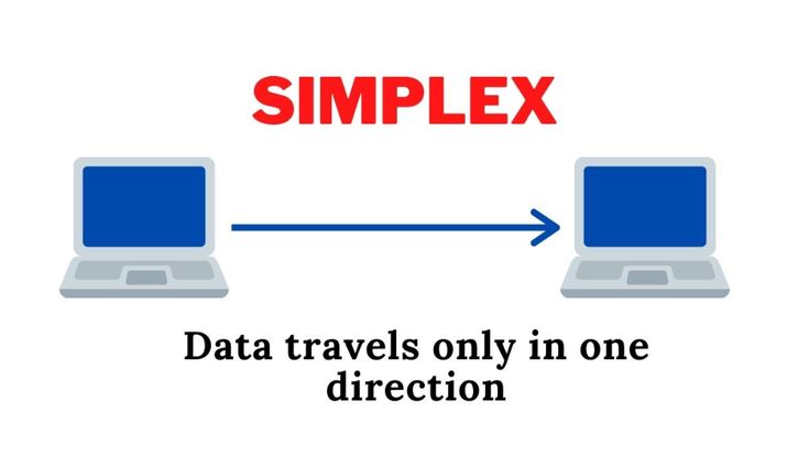
- In computing network when there is a single flow of information or one direction flow of information from the sender to the receiver is known as Simplex mode of transmission.
- In this mode of transmission, the communication takes place in one direction only, the circuit is connected in such a way that it is either send only or receive only.
- There is no other mechanism for the data to be transmitted to the sender and this mode of transmission generally includes circuits that are dedicated and are used in securities and fire alarms.
Examples
- Communication between the computer and a keyboard is a basic example of simplex transmission where the keyboard is the input and the computer is the output.
- The Speaker system is also an example of simplex transmission where the microphone acts as input and the speaker as output.
Advantages
- The main advantage is that the capacity of the communication channel can be fully utilized when transmission happens between two devices.
- In a simplex mode of transmission, the radio stations can utilize the entire bandwidth of the communicating channel so that all the data can be transmitted in one shot without any data loss.
Disadvantages
- Since the communication between devices is unidirectional, so there is no intercommunication between two devices.
- The simplex mode of transmission is mainly used in business fields where the quick reply is not required as communications mainly perform two-way exchange of data.
2. Half Duplex Transmission Mode
- In computing networks when there is both way flow of information or both direction flow of information from the sender to the receiver but only one at a time is known as Half duplex mode of transmission.
- In this mode of transmission, the communication takes place in both directions, the connected devices can transmit or receive the data but not simultaneously.
- The direction of communication can be reversed as the radio stations can receive as well as transmit the data and each character that is transmitted is displayed on the screen instantaneously.
Examples
- Many computer modems, printers, buffer polling falls in half duplex transmission mode.
- A walkie talkie is a perfect example of half duplex transmission. The working functionality of walkie talkie is that when one person speaks from one end, another person listens from another end. After a break, then another person speaks and the first person on the other end listens. Simultaneous speaking is not possible since this will create a distortion of sound and both the receiver and the transmitter will not able to comprehend the information.
Advantages
- Half duplex transmission is mainly used for low speed transmission involving wires and circuits.
- With the help of half duplex transmission, error detection is performed in a simpler way. If any error occurs during data transmission at any stage of time, the receiver will just provide a request to the sender to retransmit the data and the sender will acknowledge according to it.
- Since both way communication occurs through this mode of transmission, the entire bandwidth of communicating channel is utilized during transmission and in one direction at a time.
Disadvantages
- In this mode, when one mode is sending the data the opposite party must wait for the response that causes a delay in sending and receiving the data at the right time.
3. Full Duplex Transmission Mode

- In computing networks when there is both way flow of information or both direction flow of information from the sender to the receiver simultaneously is known as full duplex mode of transmission.
- In this mode of transmission, the communication takes place in both directions over a communication link where two wires are necessary and the channel capacity is shared between the two devices.
- The bi-directional communication connects the devices, receiving and transmitting at the same time and the communication link contains separate paths for sending and receiving.
Examples
- The most common example of this mode of transmission is the telephone. When two people speak or communicate through telephone by using a telephone line, both has the ability to talk and listen simultaneously.
Advantages
- The full duplex mode of transmission is the fastest mode of transmission since the transmission happens both ways simultaneously.
- The radio stations contain two separate channels, one channel is used for sending the data in one direction and the other channel for the receiver on the other end in the opposite direction.
Disadvantages
- If the appropriate link or there is the absence of any dedicated path between the communicating devices, then the channel capacity of the communicating channel is subdivided into parts and the proper utilization of bandwidth of the channels will not be maintained.
categories of Network
One way to categorize the different types of computer network designs is by their scope or scale. For historical reasons, the networking industry refers to nearly every type of design as some kind of area network. Common examples of area network types are:
- LAN – Local Area Network
- WLAN – Wireless Local Area Network
- WAN – Wide Area Network
- MAN – Metropolitan Area Network
Local Area Network
A LAN connects network devices over a relatively short distance. A networked office building, school, or home usually contains a single LAN, though sometimes one building will contain a few small LANs (perhaps one per room), and occasionally a LAN will span a group of nearby buildings. In TCP/IP networking, a LAN is often but not always implemented as a single IP subnet. In addition to operating in a limited space, LANs are also typically owned, controlled, and managed by a single person or organization. They also tend to use certain connectivity technologies, primarily Ethernet and Token Ring.
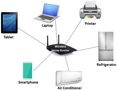
Wireless Local Area Network
As the term implies, a WAN spans a large physical distance. The Internet is the largest WAN, spanning the Earth. A WAN is a geographically-dispersed collection of LANs. A network device called a router connects LANs to a WAN. In IP networking, the router maintains both a LAN address and a WAN address.
A WAN differs from a LAN in several important ways. Most WANs (like the Internet) are not owned by any one organization but rather exist under collective or distributed ownership and management. WANs tend to use technology like ATM, Frame Relay and X.25 for connectivity over the longer distances.
OSI
The Open Systems Interconnection (OSI) model is a framework that describes the functions of a networking system. The OSI model categorizes the computing functions of the different network components, outlining the rules and requirement needed to support the interoperability of the software and hardware that make up the network.
In addition to understanding what the OSI model is, note that the OSI model layers are particularly helpful when visualizing the flow of data from the sender to the receiver. The descriptions of the various levels, as well as their interdependency, make it easier to pinpoint networking issues. Also, programmers can use the OSI model to better understand how data gets to and from their applications or to write code specific for use at certain levels.
The 7 Layers of the OSI Model
There are seven abstraction layers that make up the OSI model. Communication from one person to another goes from Layer 7 to Layer 1. Each layer performs a specific job before it sends the data on to the next layer.
Application Layer
The application layer is the closest to the end-user. It initiates communication between the user and the applications they personally interact with. At this layer, data is translated from the syntax it was converted to into something the user can read.
Examples of Layer 7 applications include a web browser like Chrome, Safari, or Firefox, or an email application. Layer 7 can also identify communication partners, check to see which resources are available, and make sure communication is properly synced.
Presentation Layer
The presentation layer takes care of getting data ready for the application layer. The two devices that are communicating may use different methods of encoding their data. Layer 6 therefore turns the incoming data into something that can be read at the application layer. This includes encrypting and decrypting data.
The presentation layer also compresses data that comes from the application layer before it sends it on to Layer 5, the session layer.
Session Layer
The session layer handles opening and closing network communications between two interacting devices. The “session” refers to the time between the opening and closing of the interaction. The session layer makes sure the session is open for a long enough period of time for all the necessary data to be sent through. The session layer then closes the session to prevent expending unnecessary resources.
Also, it synchronizes the data transfer. If a large amount of data is being sent, the session layer can set up checkpoints. If the transmission gets interrupted before all the data is downloaded, the checkpoints allow the transmission to be resumed without it starting all over again.
Transport Layer
The transport layer handles end-to-end communication between the devices interacting with each other. The management of the communication involves taking the data in the session layer and dividing it into pieces referred to as segments. The transport layer on the device receiving the communication handles the reassembly of the segments into data that is consumable by the session layer.
Also, the transport layer takes care of managing the flow and any necessary error messages that need to be sent in the event something goes wrong. To manage data flow, the transport layer makes sure it is not being sent so quickly that the receiver’s device cannot handle it. To control errors, the transport layer checks to see if the data transmitted was done so completely. If it is not, this layer will request a retransmission.
Layer 4 is where Transmission Control Protocol (TCP) and User Datagram Protocol (UDP) port numbers work. Internet Protocol (IP) addresses operate at Layer 3, the network layer. TCP, UDP, and IP are protocols that facilitate how data is sent and received.
Network Layer
The network layer facilitates the transfer of data when two networks are communicating with each other. If two communicating devices are using the same network, then there is no need for the network layer. The network layer divides the segments that come from the transport layer. These are referred to as packets. The division of the segments into packets happens on the sender’s device, and they are reassembled on the receiving device.
The network layer also functions as an efficiency tool. It figures out the optimal physical path needed to get the data to its destination. This function is called “routing.”
Data Link Layer
The data link layer is like the network layer, except that the data link layer facilitates data transfer between two devices using the same network. In the data link layer, packets are broken into pieces referred to as frames. Similar to the network layer, the data link layer handles flow and error control. The transport layer is different in that it only manages the flow of data and errors when two networks are communicating with each other.
Within the data link layer, you have two sublayers, the media access control (MAC) and logical link control (LLC) layers. The majority of switches perform their duties at Layer 2. In some cases, switches work at Layer 3 because they are facilitating communication between two networks or virtual local-area networks (VLANs). This has to happen at Layer 3 because, in these situations, the data needs to be routed, which is a Layer 3 task.
Physical Layer
The physical layer involves the physical equipment that transfers data, like switches and cables. In this layer, the data is converted into strings of 1s and 0s. In the physical layer, the devices have to agree on a method of distinguishing the 1s from the 0s, which enables the digital data to be properly interpreted by each device.
The physical layer includes a variety of components, such as cables, the radio frequency used to transmit data, Wi-Fi, and the other physical structures for transmitting data, such as pins, necessary voltages, and types of ports.

TCP/IP Models
What is TCP/IP?
TCP/IP stands for Transmission Control Protocol/Internet Protocol and is a suite of communication protocols used to interconnect network devices on the internet. TCP/IP is also used as a communications protocol in a private computer network (an intranet or extranet).
The entire IP suite — a set of rules and procedures — is commonly referred to as TCP/IP. TCP and IP are the two main protocols, though others are included in the suite. The TCP/IP protocol suite functions as an abstraction layer between internet applications and the routing and switching fabric.
CP/IP specifies how data is exchanged over the internet by providing end-to-end communications that identify how it should be broken into packets, addressed, transmitted, routed and received at the destination. TCP/IP requires little central management and is designed to make networks reliable with the ability to recover automatically from the failure of any device on the network.
The two main protocols in the IP suite serve specific functions. TCP defines how applications can create channels of communication across a network. It also manages how a message is assembled into smaller packets before they are then transmitted over the internet and reassembled in the right order at the destination address.
IP defines how to address and route each packet to make sure it reaches the right destination. Each gateway computer on the network checks this IP address to determine where to forward the message.
A subnet mask tells a computer, or other network device, what portion of the IP address is used to represent the network and what part is used to represent hosts, or other computers, on the network.
Network address translation (NAT) is the virtualization of IP addresses. NAT helps improve security and decrease the number of IP addresses an organization needs.
Common TCP/IP protocols include the following:
- Hypertext Transfer Protocol (HTTP) handles the communication between a web server and a web browser.
- HTTP Secure handles secure communication between a web server and a web browser.
- File Transfer Protocol handles transmission of files between computers.
How does TCP/IP work?
TCP/IP uses the client-server model of communication in which a user or machine (a client) is provided a service, like sending a webpage, by another computer (a server) in the network.
Collectively, the TCP/IP suite of protocols is classified as stateless, which means each client request is considered new because it is unrelated to previous requests. Being stateless frees up network paths so they can be used continuously.
The transport layer itself, however, is stateful. It transmits a single message, and its connection remains in place until all the packets in a message have been received and reassembled at the destination.
The TCP/IP model differs slightly from the seven-layer Open Systems Interconnection (OSI) networking model designed after it. The OSI reference model defines how applications can communicate over a network.
Why is TCP/IP important?
TCP/IP is nonproprietary and, as a result, is not controlled by any single company. Therefore, the IP suite can be modified easily. It is compatible with all operating systems (OSes), so it can communicate with any other system. The IP suite is also compatible with all types of computer hardware and networks.
TCP/IP is highly scalable and, as a routable protocol, can determine the most efficient path through the network. It is widely used in current internet architecture.
The 4 layers of the TCP/IP model
TCP/IP functionality is divided into four layers, each of which includes specific protocols:
- The application layer provides applications with standardized data exchange. Its protocols include HTTP, FTP, Post Office Protocol 3, Simple Mail Transfer Protocol and Simple Network Management Protocol. At the application layer, the payload is the actual application data.
- The transport layer is responsible for maintaining end-to-end communications across the network. TCP handles communications between hosts and provides flow control, multiplexing and reliability. The transport protocols include TCP and User Datagram Protocol, which is sometimes used instead of TCP for special purposes.
- The network layer, also called the internet layer, deals with packets and connects independent networks to transport the packets across network boundaries. The network layer protocols are IP and Internet Control Message Protocol, which is used for error reporting.
- The physical layer, also known as the network interface layer or data link layer, consists of protocols that operate only on a link — the network component that interconnects nodes or hosts in the network. The protocols in this lowest layer include Ethernet for local area networks and Address Resolution Protocol.
Uses of TCP/IP
TCP/IP can be used to provide remote login over the network for interactive file transfer to deliver email, to deliver webpages over the network and to remotely access a server host’s file system. Most broadly, it is used to represent how information changes form as it travels over a network from the concrete physical layer to the abstract application layer. It details the basic protocols, or methods of communication, at each layer as information passes through.
